
Shearing, also called trimming, is the first step in the production of three-piece cans and is a process in the manufacture of printed tinplate cans. Its purpose is to cut pre-printed and coated multi-die sheets into individual small pieces of the specified size to meet the requirements of the subsequent resistance welding process.
Because resistance welding machines require high shearing accuracy, disc shearing technology is commonly used today. Traditional manual shearing is no longer in use; currently, double-action disc shearing machines are standard. New cutting machines can quickly adjust the sheet size as needed: by simply inputting the required commands into the software, the desired sheet size can be cut. However, completely replacing traditional disc shearing machines may still take some time.
The mainstream shearing equipment currently used domestically comes from Italy, Taiwan, and domestic light industrial regions. With the rapid development of the can-making industry, shearing machines are continuously being upgraded to meet market demands.
Components of Shearing Equipment:
By Function: automatic sheet feeder, bi-directional double-action rotary shearing machine, and the widely used robotic devices for automatic collection, conveying, and feeding, compatible with resistance welding machines.
By Control System: electrical control system, safety protection system, mechanical positioning and synchronized conveying system, and bi-directional double-action rotary cutter assembly (attachment: rotary cutter grinding device).
Bi-directional shearing means the first cut divides the vertical can body circumference, and the second cut divides the horizontal can body height (see Fig. 3-30). To accommodate different can types and printing layouts, a sufficient number of rotary cutters must be installed. Shearing machines are generally equipped with seven pairs of cutters for the first cut and nine pairs for the second cut, which basically meets production requirements.
In the example provided, the sheet is first cut into strips (e.g., 1, 2, 3, 4, 5) by the first set of rotary cutters (Fig. 3-31), then each strip is sequentially cut into small individual pieces (e.g., 1, 2, 3, 4, 5, 6, 7) by the second set of rotary cutters (Fig. 3-32).
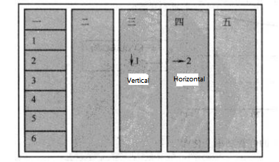
Figure 3-30 Schematic of 5×7 Layout for Printed Sheet Material
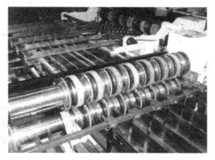
Figure 3-31 Transverse Shearing

Figure 3-32 Longitudinal Shearing
Shearing Machine Workflow: Controlled process completed through the steps of sheet suction feeding → double-sheet detection → double-sheet ejection → conveying and counting detection → positioning → first shearing → reversing conveyance → positioning → second shearing → material collection.
The material feeding rack of the shearing machine is shown in Figure 3-33.
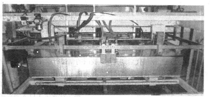
Figure 3-33 Material Feeding Rack
The quality inspection items for sheared products mainly include: width and length of the cut pieces, squareness, curved plates (also called sickle bends), burrs, as well as the reserved edges for welding and the appearance of the printed/coated surfaces. The minimum width of scrap edges is required to be 1.0 mm (note: edges that are too narrow may cause blade jamming and obstruct normal production). The size of the scrap edges can be set by adjusting the positioning fixed edge guide rollers. The above inspection items can be measured using a flat plate gauge and a vernier caliper, with tolerances referring to the relevant national standards or suitable internal standards based on actual production requirements.
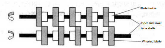
Figure 3-34 Upper and lower rotary knives
The grinding of rotary knives should be performed according to the relevant equipment manuals. The structure of the upper and lower rotary knives is shown in Figure 3-34.
Currently, most high-speed welding machines use robotic arms for automatic feeding of sheet material. However, when manually feeding sheets into the welder, care must be taken to prevent contamination of the can body sheets. Sheets that are left unused for too long or stored improperly may develop rust at the cut edges, which can affect welding quality.
Common issues in sheet cutting and their remedies are as follows:
- Adjusting knife spacing for different product specifications:
Use the first pair of upper and lower knives on the left as the reference cutting line. Loosen the bolts of the other knife holders, then move each pair of knives sequentially to the required cutting positions according to the product size. Set the blade gap using feeler gauges, then lock the knife holders in place. Afterwards, adjust the relevant receiving chute or guide rods to match production requirements.
- Changes in sheet specifications:
Adjust the positioning side gauge and the magnetic sheet separator on the feeding rack to ensure normal production.
- Excessive width and height deviations:
Mainly corrected by adjusting the spacing between the knives to meet the specifications. Typically, can body circumference $L$ should be ±0.05 mm and can height $H$ should be ±0.10 mm.
- Excessive burrs at cut edges:
Adjust the gap between upper and lower knives and grind any dull blade edges. The blade gap should be 0.02–0.03 mm, blades must be smooth and continuous without notches, and burrs should be ≤0.15 Tb (Tb = can sheet thickness). Maintain correct burr orientation: along the forming direction, burrs should be on the inner side of the can body overlap; along the can height, burrs should avoid the inner side of the can’s aluminum bottom/cover. This ensures weld quality and proper sealing for double-rolled aluminum ends.
- Excessive squareness deviations (crooked sheets):
Usually caused by the positioning edge not being perpendicular to the knife shaft, or uneven feeding force between double push claws. Check visually for size differences at the ends of scrap edges or overlap small sheet pieces from both sides to check for diagonal misalignment. Squareness can also be measured with a squareness gauge. Typically, deviation should be ≤0.10 mm over a 100 mm measurement along the vertical edge.
- Uneven welding allowance edges:
Adjust the positioning edge to distribute scrap width evenly. The pressure of the pushing edge should be moderate to avoid sheet expansion or misalignment.
It must be emphasized that ensuring the quality of the cut can body sheets is essential to achieving high-quality welds.