
In the past 20 years, such equipment was mainly manufactured by two Swiss companies, as shown in Figs. 3-104 and 3-105. In recent years, new manufacturers have also emerged. The equipment is mainly composed of two systems: a powder processing system and a pipeline system.
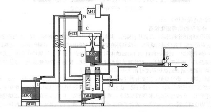
Fig. 3-104 EPC Powder Repair Coating Equipment – Schematic Diagram
The pipeline system includes a spray coating arm, powder spray pipe, inner powder suction pipe, high-voltage cable pipe, cleaning high-voltage needle air pipe, and the OHC external powder suction device.
The powder processing system consists of a raw powder tank, powder filtration tank, cyclone powder processor, exhaust fan, repair coating powder tank, high-voltage electrostatic system, and PLC monitoring and control system.
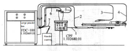
Fig. 3-105 UNICO ATP60 Powder Repair Coating Equipment – Schematic Diagram
1 – Powder inlet pipe 2 – Powder return pipe
3 – External powder return pipe 4 – Cleaning powder return pipe
5 – Small powder tank inlet pipe 6 – Small powder tank return pipe
7 – Large powder tank inlet pipe
Working Principle
The powder is drawn from the raw powder tank or raw powder bucket into the filtration tank by vacuum negative pressure generated by the exhaust fan or suction gun. After passing through a powder filter screen and cyclone powder processor, the powder particles are adjusted to the appropriate size for repair coating and cleaned. To prevent powder from being released into the production environment, a high-density filter is installed in front of the exhaust fan to separate air and powder. Meanwhile, in the filtration tank, a small airflow fluidizes the powder.
When required by the repair coating powder tank (detected by sensors), the treated powder is conveyed by airflow from the filtration tank to the repair coating powder tank. During welding operation, the welding machine sends a signal to the repair coating equipment, simultaneously opening the spray airflow and valve of the repair tank. The powder is then carried by airflow to the spray arm. At the spray arm outlet, a high-voltage needle emits static electricity at 20–40 kV. When the powder coating passes through this high-voltage field, the powder particles become charged and, under the action of airflow and the electrostatic field, adhere to the can wall along the welded seam area. At the spray outlet, a pair of lips seals the edges to prevent powder from spreading outward, ensuring a neat repair coating strip. The higher the electrostatic voltage, the better the powder adhesion.
During coating, the excess powder between cans is collected by the OHC external suction device and returned to the filtration tank for reuse. Additionally, powder falling at the spray arm area is collected by a bottom suction device and returned to the filtration tank, minimizing waste.
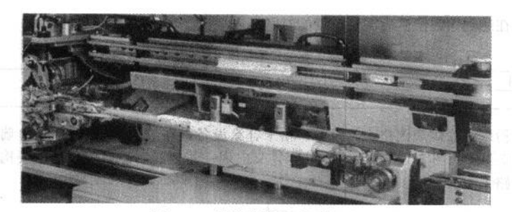
Fig. 3-106 Connection Between Powder Spray Arm and Welding Arm