
Inspection
(1) Surface Quality – Visual Inspection
Visually inspect the steel sheets. The tin coating should be uniform and smooth, without scratches, dents, wrinkles, rust spots, or other defects that may affect usability.
(2) Thickness
① Micrometer Method:
Use a micrometer with a measurement accuracy of 0.001 mm.
When measuring the thickness of the steel sheet, the distance from the edge in the rolling direction should be no less than 10 mm.
When measuring the transverse thickness distribution (thin edges), the distance from the edge in the rolling direction should be no less than 6 mm.
Thickness is usually measured using a micrometer. In case of dispute, the weighing method shall prevail.
② Weighing Method

(2) Thickness (continued)
The weight of the steel sheet shall be measured with an accuracy of 2 g.
The length and width of the steel sheet shall be measured with an accuracy of 0.5 mm.
Thickness shall be calculated with an accuracy of 0.001 mm.
The average thickness of the batch is determined by calculating the average thickness of all sampled steel sheets.
One specimen is taken from the center and one from the edge of the test steel sheet. The thickness of each is determined using the weighing method to assess thickness variation within a single sheet (see Figure 5-1 for sampling locations).
The specimen weight is measured with an accuracy of 0.01 g.
The specimen length and width are measured with an accuracy of 0.1 mm.
Thickness is calculated with an accuracy of 0.001 mm.
(3) Length and Width
To verify the length of coil sheets, the buyer calculates the total length by multiplying the average length of sheared steel sheets by the total number of sheets, then adding the length of any remaining coil parts.
A minimum of 10 steel sheets shall be randomly selected to measure average length, with a measurement accuracy of 0.2 mm.
Other methods agreed upon by both parties may also be used.
To measure the width of coil sheets, place the steel sheet on a flat surface and measure across the center, perpendicular to the rolling direction, with an accuracy of 0.5 mm.
For both length and width measurements, the steel sheet shall be placed flat, and the measurement taken across the center, with an accuracy of 0.5 mm.

X – Tin Coating Sample
Y – Hardness and Same Sheet Variation Sample
Z – Tensile or Rebound Sample
(4) Shape Deviation
① Camber:
The camber of the steel sheet should not exceed 0.15% within 1000 mm.
For coil sheets, the camber measured over a 6000 mm chord length should not exceed 6 mm, or over a 1000 mm chord length, it should not exceed 1 mm.
② Edge Slant:
The edge slant should not exceed 0.15%.
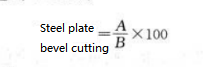
In the formula
A — Deviation
B — Length or Width of Steel Sheet
③ Flatness: The flatness of the steel sheet over 1000 mm should not exceed 3 mm.
Cold-rolled tinplate may exhibit phenomena such as burrs, edge waviness, longitudinal curvature, or transverse curvature. The standard GB/T 2520—2000 does not specify measurement methods or allowable limits. Allowable limits may vary depending on the equipment used by the buyer.
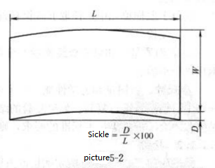
Figure 5-2
L — Chord Length
W — Rolling Width
D — Deviation from the Relative Straight Line
(5) Tin Coating
For each steel sheet to be inspected, take three samples perpendicular to the rolling direction from the edge, center, and edge areas. The distance from the edge sample to the edge line should be no less than 25 mm. Measure the area of each sample accurately.
Sample Cleaning:
a. Perform cathodic treatment in a 0.5% sodium carbonate solution;
b. Wipe the sample with acetone-soaked degreasing cotton.
Tin Coating Measurement
The tin coating is expressed in g/m², with an accuracy of 0.1 g/m².
For daily quality control, any recognized applicable method can be used to measure the tin coating. In case of dispute, the capacity method specified in GB/T 1838 shall be used.
The tin coating of a batch is the average value of the tin coating for all individual samples. The measured tin coating value for an individual sample cannot represent the tin coating of the entire batch; it can be as low as 80% of the minimum average tin coating value.
① Capacity Method:
Also known as the iodometric method, this is the arbitration method for measuring tin coating. The method involves dissolving the cleaned and treated tinplate sample in hydrochloric acid, reducing all the tin to its divalent state with aluminum, and then titrating with a standard potassium iodate solution to determine the amount of reduced tin.
The reproducibility of this method is ±0.1 g/m², with an effective measurement range of 2.5–50 g/m². For measurements exceeding this range, an appropriately concentrated potassium iodate solution should be prepared to ensure a suitable titration volume.
② Coulometric Method:
The coulometric method is a conventional method for measuring tin coating. It is based on the principle that 1C of electrical charge can separate a specific amount of tin from the tinplate. A tinplate sample is used as the anode, with an electrode component as the cathode. In a 1 mol/L hydrochloric acid electrolyte solution, tin is gradually removed from the coating at a constant rate using an opposite current. Once the voltage is set, the system automatically detects the point where all the tin from the tin coating and alloy layer has been completely dissolved.
By recording the potential difference between the sample and the silver reference electrode relative to time, the corrosion time and coating thickness are in a linear relationship. Using Faraday’s law of electrolysis, the amount of free tin and alloy tin can be calculated.
Figure 5-2 shows the T-V (time-voltage) relationship for the #25 tinplate electrolysis.
The electrolytic tin consumption formula is:
Q = IT
Free Tin Amount=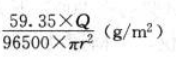
Alloy Tin Amount=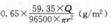
Total Tin Coating = Free Tin Amount + Alloy Tin Amount
In the formula
I — Electrolytic de-tinning current, A
T — Electrolytic de-tinning time, s
r — Radius of the de-tinning area, m
0.65 — Constant for the current required to remove alloy tin
The accuracy of tin coating measurement during the process is determined by these three parameters.
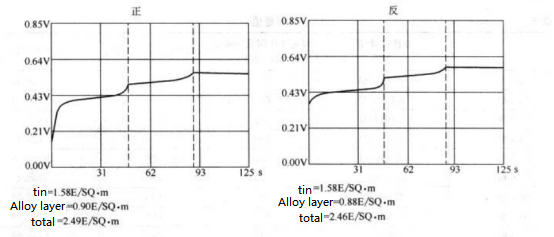
Figure 5-3 #25 Tinplate Electrolytic De-tinning T-V (Time-Voltage) Curve
a. Accuracy of the de-tinning area;
b. Accuracy of the current;
c. Accuracy of the time measurement.
(6) Hardness
Hardness testing is performed on samples used for measuring the same plate difference. For arbitration tests, the sample should first have the tin coating removed, undergo artificial aging at 200°C for 20 minutes, and then be tested according to GB/T 1818.
For tinplates with a thickness not exceeding 0.22 mm, it is recommended to use the HR15T scale for testing. The test results should be converted and expressed in HR30Tm.
The hardness of a batch is the average hardness of all individual samples. The deviation of a single sample’s hardness value from the average range should not exceed one hardness unit.
(7) Mechanical Properties of Cold-Rolled Electrolytic Tinplate
① Tensile Test:
The tensile test is the standard method for measuring the mechanical properties of cold-rolled electrolytic tinplate using a testing machine.
Two samples (200 mm × 25 mm) are taken from each test steel plate at the edge and center, along the rolling direction, with the distance from the edge sample to the edge line being no less than 25 mm. Prior to testing, artificial aging is performed at 200°C for 20 minutes.
A tensile test is conducted according to GB/T 228—2002, using samples with a width of 12.5 mm × 1 mm and a gauge length of 50 mm to measure the specified non-proportional elongation strength. The measured values are shown in Table 5-1. Figure 5-3 shows the mechanical performance measurements (deformation force) for 0.15 mm cold-rolled plates.
② Rebound Test:
For daily measurement of the mechanical properties of cold-rolled tinplate, the rebound test is used instead of the tensile test. The rebound test is not the standard method; in case of dispute, the tensile test shall be considered authoritative.
Two 200 mm × 25 mm samples are taken from each test steel plate at the edge and center, along the rolling direction, with the distance from the edge sample to the edge line being no less than 25 mm. Prior to testing, artificial aging is performed at 200°C for 20 minutes.
The thickness of the samples is first measured to an accuracy of 0.001 mm, and the samples are fixed in the rebound tester. The balance swing forming arm bends the sample 180° around the central axis, returning to the starting position. The rebound index (SBI) is then measured using the corresponding curve chart on the rebound tester, based on the sample thickness and rebound angle.
The conversion formula is:
Rp = 6.9 × SBI (N/mm²)
Metal Iron Sheet Room Temperature Tensile Test Report
Sample Width (b): 12.5 mm
Sample Thickness (a): 0.15 mm
Original Gauge Length (Lo): 75 mm
Extensometer Gauge Length (Le): 50 mm
Specified Non-Proportional Elongation Rate (Rp): 0.2%
Standard Followed: GB/T 228—2002
Table 5-1
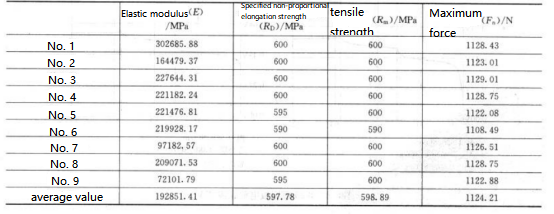
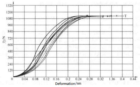
5-40.15mm Cold-Rolled Tinplate Mechanical Property Measurement Values (Deformation Force)
(8) K Plate Iron Dissolution Value (ISV)
① Experimental Principle: Under simulated low-oxygen conditions in a can, the exposed iron on the sample reacts with ammonium thiocyanate to form a blood-red ammonium ferric thiocyanate complex. Under appropriate conditions, the depth of the color is proportional to the concentration of dissolved iron ions. The ISV value is quantitatively determined by colorimetric comparison with a standard iron solution. The ISV reflects the uniformity of the tin layer on the tinplate, indicating the degree of exposed iron. The higher the ISV value, the more iron exposure points there are.
This test is applicable to tinplate with a tin coating of no less than 5.6g/m².
② Reagents:
a. Pure iron powder: also known as reduced iron powder, analytical grade;
b. Ammonium thiocyanate: analytical grade;
c. Concentrated sulfuric acid: relative density 1.84, concentration 98%, analytical grade;
d. Concentrated nitric acid: analytical grade;
e. Hydrogen peroxide solution: 30% concentration, analytical grade;
f. Sodium carbonate: chemical or analytical grade.
③ Apparatus and Tools:
a. DC power supply: output voltage 0-30V, output current 0-5A, adjustable;
b. 751GD UV-Vis spectrophotometer;
c. Test cup: custom-made;
d. Constant temperature incubator: accuracy ±0.1°C, adjustable between 0-50°C;
e. Glassware: 50mL colorimetric tube, 25mL pipette, 1mL, 2mL, 10mL pipettes, 100mL, 500mL, 1000mL volumetric flasks, beakers, reagent bottles, glass rods, etc.
④ Preparation of Test Solutions:
a. 2.18 mol/L Sulfuric Acid: Take 30.5mL of concentrated sulfuric acid and dilute to 500mL, making the volume up to 500mL in a volumetric flask. Store in a 500mL stoneware bottle.
b. Ammonium Thiocyanate Solution: Weigh 20.0g of ammonium thiocyanate, dissolve in 500mL of water, and make up the volume to 500mL in a volumetric flask. Store in a 500mL stoneware bottle.
c. 3% Hydrogen Peroxide Solution: Accurately take 5mL of 3% hydrogen peroxide, dilute with water to 50mL, make up the volume to 50mL in a volumetric flask, and store in a 50mL brown reagent bottle.
d. 0.5% Sodium Carbonate Solution: Weigh 5g of sodium carbonate, dissolve it in 1000mL of water, and keep it in an electrolytic cell or 1000mL beaker for use.
e. 1:1 Hydrochloric Acid Solution: Prepare a 10mL 1:1 hydrochloric acid solution by volume.
⑤ Sample Treatment:
a. Sampling: From the sample tinplate provided for the test, cut out a circular sample with a diameter of approximately 69mm, according to the sample’s tin layer thickness test location or its vicinity.
b. Cleaning: Electrolytic cleaning of the sample in a 0.5% sodium carbonate solution, using a carbon rod as the positive electrode and the sample as the negative electrode. Apply a current of 1.5\~2.0A for 30 seconds (time may vary depending on oil content). After removing the oil, rinse with distilled water and dry with acetone.
c. Etching: Accurately measure 23.0mL of 2.18 mol/L sulfuric acid, 2.0mL of 3% hydrogen peroxide solution (freshly prepared), and 25.0mL of ammonium thiocyanate solution into the cleaned test cup. Place the cleaned sample face-down on the cup’s gasket, secure the lid, and invert the cup. Place it in a constant temperature incubator at 26.7°C (±2.8°C) for 2 hours.
⑥ Analysis Procedure:
a. Adjustment of the Spectrophotometer
(a) Select the tungsten lamp, turn on the power switch, and let the instrument warm up for 30 minutes. Then adjust the wavelength knob to 485 nm.
(b) Adjust the instrument as required and keep it ready for use.
b. Preparation of Iron Standard Curve
(a) Preparation of iron standard stock solution: Accurately weigh 0.15 g of pure iron powder using an analytical balance into a clean beaker. Dissolve it with gentle heating in 1:1 nitric acid solution until completely dissolved. After the iron powder has fully dissolved, add 5 mL of concentrated sulfuric acid and heat until fumes appear. After cooling, add 55.6 mL of concentrated sulfuric acid, then dilute with distilled water to a final volume of 1000 mL.
(b) Preparation of iron standard working solution: Accurately measure 10.0 mL of iron standard stock solution, dilute with 2.18 mol/L sulfuric acid (1/2 H₂SO₄) to a final volume of 100 mL.
(c) Preparation of standard solutions for colorimetric measurement: Prepare standard solutions as required in Table 5-2.
Table 5-2 Preparation of Standard Solutions
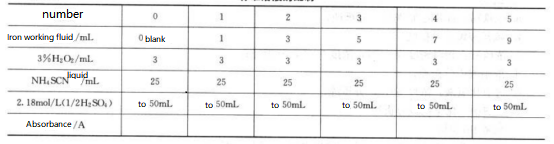
(d) Measurement: Place the colorimetric solutions numbered 0 to 5 into 2 cm cuvettes in order of increasing concentration (up to four cuvettes at a time). Use the blank cuvette (No. 0) to perform zero calibration. After zeroing, press the MOVE key to display the absorbance (A) value. Then measure the absorbance values of both the standard solutions and the sample solutions, recording the A values accordingly.
(e) Standard curve plotting: Use the absorbance (A) values as the x-axis and the iron ion concentration as the y-axis. Plot the points corresponding to the measured A₁, A₂, A₃, A₄, A₅ and their respective iron concentrations, then draw the best-fit straight line passing through the origin.
(f) Determination of sample iron ion content: Using the standard curve and the measured sample absorbance (A), find the corresponding iron ion microgram amount on the curve.
⑦ Calculation:
ISV=
⑧ Note:
The actual area can be determined by measuring the diameter of the corroded circle.
(9) K-plate tin grain size (TCS)
① Test principle:
The tin grain size reflects the influence of grain size on corrosion resistance; generally, tin-coated plates with larger grains have better corrosion resistance. The tin grain size mainly depends on the soft melting process during tinplate production. The tin grain size is not easily visible to the naked eye but becomes clearly visible after etching with ferric chloride and sodium sulfide solution.
Applicable to tinplate with a tin coating of not less than 5.6 g/m².
② Reagents:
a. Sodium carbonate: analytically pure
b. Ferric chloride: analytically pure
c. Sodium sulfide: analytically pure
d. Acetone: analytically pure
③ Instruments and equipment:
a. DC power supply: output voltage 0–30 V, output current 0–5 A, adjustable
b. Glassware: 500 mL beaker, evaporating dish, glass rod, etc.
④ Preparation of test solutions:
a. 0.5% sodium carbonate solution (electrolyte)
b. Test solution (contains 100 g ferric chloride and 0.75 g sodium sulfide per liter)
⑤ Test method:
a. Sample preparation: cut a 7 cm × 7 cm sample, degrease with acetone, then place in a container filled with the electrolyte. Using a carbon rod and the sample as electrodes, repeatedly clean under 10 V DC with 0.1 s anodic and 2 s cathodic cycles until the sample surface is free of water droplets.
b. Grain display: immerse the treated sample in the test solution at room temperature for 5 to 15 seconds to reveal the grains. Remove, rinse, and compare with a standard plate to assess the grade.
⑥ Evaluation method:
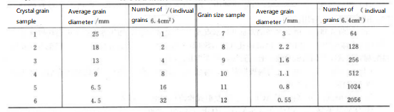
Determine the sample grade by comparing with Table 5-3.
Table 5-3 Grain diameter and grain count for each sample grade (per 1 in² or 6.4 cm²)
⑦ Acceptance criteria:
According to the above table, tinplate with larger grain size generally has better corrosion resistance. The usual requirement is not greater than grade 9 (i.e., grain diameter not less than 1.6 mm).
Note: This test is generally used for tinplate of grade ≥ 50#.
(10) K-plate alloy-tin galvanic coupling (ATC)
① Test principle:
The alloy-tin galvanic coupling test (ATC test) evaluates the uniformity and compactness of the alloy layer by measuring the current generated between the alloy layer and pure tin on the tinplate. The smaller the coupling current, the better the compactness; conversely, the larger the current, the poorer the compactness.
Applicable to electroplated tinplate with a tin coating not less than 5.6 g/m².
② Instruments and reagents:
a. Instruments: 50×120 mm² stainless steel plate (one piece), double-pole double-throw switch (one), wires (several), two 500 mL beakers, one 500 mL wash bottle, one 100 mL evaporating dish, one brush, one asbestos net, adjustable resistance electric furnace, sulfuric acid paper (several sheets), paper cutter (one), pure tin wire (100 cm²), copper wires (several), test cell (1400 mL), nitrogen cylinder with pressure reducer (one), temperature control device (one), foot-operated shear machine (one), measurement circuit (including 250 Ω ×1, 100 Ω ×1, 51 Ω ×1, 24 Ω ×1), adjustable DC stabilized power supply (SK1731SL5A), AC15 type DC double beam galvanometer (AC15/4).
b. Reagents: 0.5% sodium carbonate solution, 5% sodium hydroxide solution, acetone, beeswax, stannous chloride, 28% tomato ketchup or 100% grapefruit juice, potassium sorbate, 99.99% high purity nitrogen.
③ Experimental method:
a. Sampling: Cut 12–15 samples sized 8 mm × 100 mm from the specified sampling locations on the tinplate.
b. Cleaning: Degrease with acetone. Then use the sample as the anode and stainless steel plate as the cathode in 0.5% Na₂CO₃ solution, apply 10 V DC with 0.1 s anodic and 3 s cathodic cycles, repeat cleaning three times. When rinsing with water, the sample surface should be free of water droplets to be considered clean.
c. Tin removal: At room temperature, use the cleaned samples as anode and stainless steel as cathode in 5% NaOH solution. Perform electrolytic tin removal under 0.4 V DC constant voltage. Near the endpoint (when current reaches zero), reduce voltage to 0.2 V and continue tin removal for 1–2 minutes until only the alloy layer remains. Rinse and quickly dry with acetone.
d. Paper cutting: Cut 12–15 strips of sulfuric acid paper sized 5 mm × 200 mm.
e. Wax coating: Apply beeswax to all parts of the sample except the test area of 5 mm × 40 mm. During waxing, heat gently with electric furnace until beeswax just starts to smoke, then apply a uniform layer. For edges and corners, apply wax 2–3 times to ensure full protection outside the test area. (Note: for differential thickness tinplate, the test area should be on the high-tin side.)
f. Welding: Weld the wax-coated samples onto rubber stoppers with copper wires using a soldering iron.
g. Connection:
(a) Disinfect the test cell: Boil all rubber parts in 10% NaOH solution for 5 minutes before the test and rinse thoroughly. The test cell and all accessories must be thoroughly disinfected.
(b) Tin electrode cleaning: Clean in 0.5% Na₂CO₃ solution using 10 V DC with 0.1 s anode and 3 s cathode cycles, repeated three times, then rinse with water and keep ready.
(c) Preparation of test solution: Dilute 28% tomato ketchup with nine parts water or use 100% grapefruit juice, boil and keep slightly warm for 15–20 minutes to remove oxygen. Cool to 28°C. Add 0.190 g stannous chloride (SnCl₂·2H₂O) and 0.5 g potassium sorbate, dilute to 1000 mL. Pour the prepared solution into the test cell, bubble nitrogen, and let stand for 24 hours before use.
(d) Insert samples: Short-circuit each of the 8 samples with the tin electrode one by one, then insert into the test cell. After all samples are coupled with the tin electrode, bubble nitrogen, maintain at 26.7°C for 20 hours.
h. Current measurement: After 20 hours, measure the ATC value with an AC15/4 DC double beam galvanometer.
④ Result determination:
ATC ≤ 0.12 μA/cm² (GB/T 2520—2000).